|
|
|
#1
 09-12-10, 19:00
|
||||
|
||||
|
Quote:
__________________
Wayne 1959 Royal Ordnance FV1611A 
|
|
#2
09-12-10, 19:06
|
||||
|
||||
|
As can be seen the front wings/ lockers are badly perished and the rear off side locker/ locker arrangement is of a similar end.
I would imagine the hardest part will be the front lockers/ arrangements to replicate?
__________________
Wayne 1959 Royal Ordnance FV1611A
|
|
#3
10-12-10, 12:56
|
||||
|
||||
|
Wayne, my wings although a bit buckled & rusted in corners were remarkably good. I replaced the locker lids which were a bit dented. The NOS replacements were of a later type. The discerning eye can identify that because on the hasp hinge the ratio of hasp width in the hinge itself to locker portion of the hinge changed making it less likely to fracture at the hinge. But with practice you can spot the difference.
The main portion of the wing should be easier to fabricate than the lockers. What you have to watch is that the locker hole has an everted lip to reduce water ingress. Never likely to be entirely successful in that the locker has a drain hole. The main underneath ribbing for the wing is provided by two U channels spot welded on. On the Mk 1 it is cruciform & you will usually see this pattern from hollowing on the top where people have stood on the wings. Mk 2 had the same up to the point that a replacement was needed, with no locker it is a slightly thicker material & the two channels run parallel. You can see this on the left of the third picture. The gubbins pieces supporting the lockers are a nightmare, but there are some usable/patterns here.      
__________________
Clive Elliott GW4MBS (Old) South Wales UK
|
|
#4
10-12-10, 13:46
|
||||
|
||||
|
More great pictures and thank you. I must confess I hade no idea how much hard work you had done to FV1609.
I have seen the X reinforcement under the wing on the air intake side as it is intact and I have rested on it peering into the engine bay before. The nearside one is Kerry Packered I must admit! I have seen the stepped edge on the locker lids and wonder from your description if this coincides with a slight projection to the liner insert that is the locker bin itself so that the lid 'nests' over the upstand to prevent weather ingress? I have highlighted what can just about be seen to be an upstand where the arrow is pointing?? But I am speculating.
__________________
Wayne 1959 Royal Ordnance FV1611A
|
|
#5
10-12-10, 14:01
|
||||
|
||||
|
Yes the everted edges of the locker orifice mate with the raised lid profile. This what you have identified.
Classic car body restoration suppliers have a range of hand operated bending gadgets which might do the fancy bits. For simple bends I have one of these. With care you can do a long run or dismantle for small pieces as it comprises 3 pieces of unequal lengths. Looks better than the vice marked metal on one piece & a "hammered effect" on the other! http://cgi.ebay.co.uk/150mm-SHEET-ME...item2c592c4d93
__________________
Clive Elliott GW4MBS (Old) South Wales UK
|
|
#6
10-12-10, 14:30
|
||||
|
||||
|
Thats a clever little impro for a bench vice! The only limitation would be sections only 150mm wide / long. Another option could be a small gauge angle profile that can be tack welded underneath as the angles can be purchased a small as 12x12mm or even 10x10mm / 3/8"x3/8".
I will end up doing some simple fabrication drawings as a master to fabricate from so will share these with you once they are done! Regards Wayne
__________________
Wayne 1959 Royal Ordnance FV1611A
|
|
#7
10-12-10, 14:52
|
||||
|
||||
|
Wayne I have a large B&Q not far away that is useful for small quantity metal products. It beats wasting half a day driving into the city to queue up at a trade counter where they don't want to sell diddley quantities to the public anyway.
Besides if you overbuy in B&Q you can take it back for a refund. But I have learnt not to do that, as excess bits will always be needed for something eventually. You're too young to know about this, but some of us get 10% off on Wednesdays  With the exception of brake pipes, I also get my plumbing there. 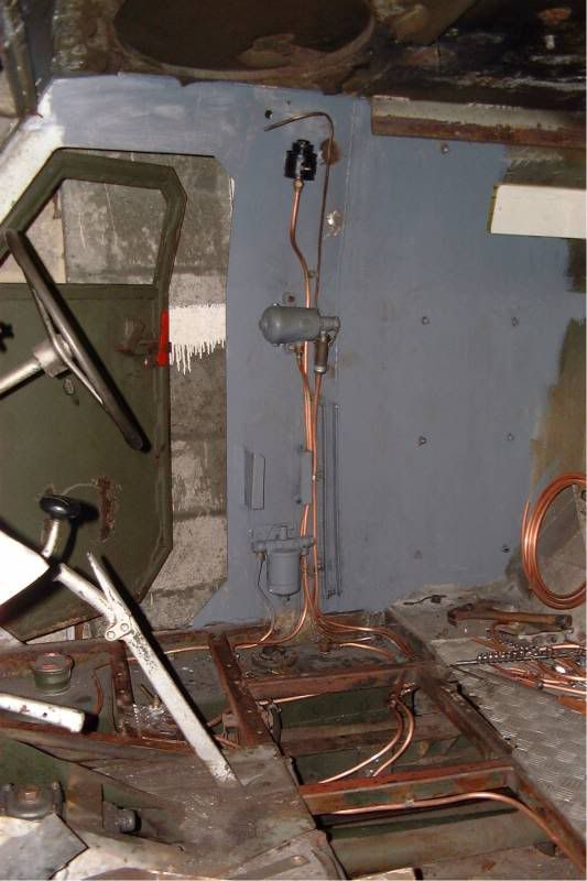 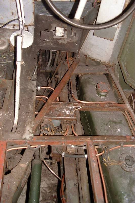
__________________
Clive Elliott GW4MBS (Old) South Wales UK
|
|
#8
11-12-10, 17:24
|
|||
|
|||
|
Quote:
__________________
Terry Warner - 74-????? M151A2 - 70-08876 M38A1 - 53-71233 M100CDN trailer Beware! The Green Disease walks among us!
|
 |
| Thread Tools | |
| Display Modes | |
|
|


 Hybrid Mode
