|
|
|
#1
 06-02-11, 12:12
|
||||
|
||||
|
Google ALBERTA SPRINGS ask for Graham. They have made me several motorcycle fork springs from patterns, and can adjust the finished length to your specification to allow for wear in the original pattern. I highly recommend them. For price comparison, a single fork spring in say .007" wire is about £35 but cheaper for small batches. Ron

|
|
#2
06-02-11, 12:58
|
|||
|
|||
|
Hey Ron, thanks for that its very useful. as I live in the UK I am goign to try to source something here for obvious reasons, but will make a not of Alberta and revert to them if needs be. Thanks once again. Andrew
|
|
#4
06-02-11, 14:28
|
|||
|
|||
 Its sunday! My brain goes to sleep on a sunday! thanks a lot will take a look now. cheers! Its sunday! My brain goes to sleep on a sunday! thanks a lot will take a look now. cheers!
|
|
#5
06-02-11, 16:27
|
|||
|
|||
|
I can recommend Alberta too, though I've never had anything made as small as 0.007" wire.........

__________________
Adrian Barrell
|
|
#6
06-02-11, 21:12
|
||||
|
||||
|
I don't know what I was dreaming about there Adrian. I just had a small batch of BSA WM20 fork springs made. They are somewhere near 5/16" wire. I'm not sure if there is a wire gauge but I think there's a 7 in there somewhere?? Ron
|
|
#7
06-02-11, 21:18
|
|||
|
|||
|
It's ok Ron, I thought it was a slip of the keyboard, I couldn't think of a spring on a bike that fine!
__________________
Adrian Barrell
|
|
#8
01-06-11, 18:30
|
|||
|
|||
|
I am struggling a bit with the fabrication of the front wings for the T16 right now. If anyone out there can help I would be very grateful. The problem is that there is a curvature up in the front wing to encompass the front idler wheel. what I had on my T16 was incorrect having been changed years ago , and now I cannot really work out how it all fits together. There is a small fixed part of the fender which is horizontal and welded to the hull. I know the length and width of this , but where the problem that I think this may kick upwards towards the front of the vehicle, just where the detachable front fender bolts to it. If I dont get this correct I will not get the kick up right. Can anyone help please?
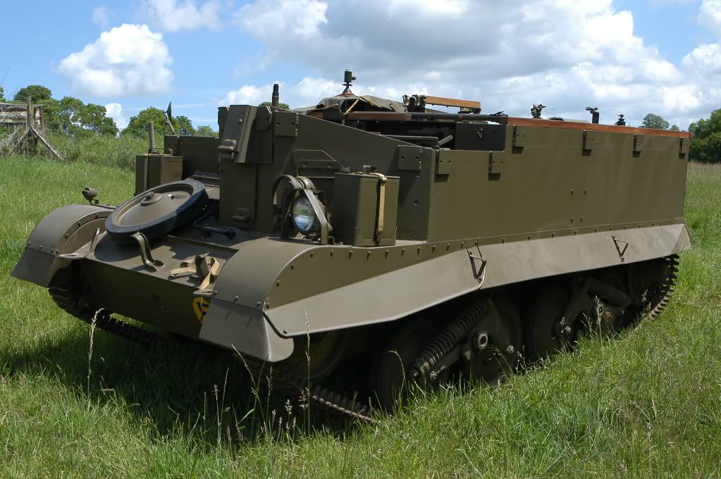  if this works it will illustrate the kick up, but how that is arranged I cannot tell from my T16.
|
|
#9
01-06-11, 18:42
|
|||
|
|||
|
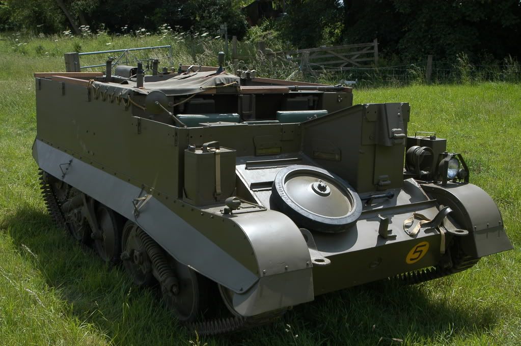
here is another photo which may illustrate what I am talking about
|
|
#10
01-06-11, 19:14
|
||||
|
||||
|
Not really sure how to measure or even accurately describe that curve. It is very minor though. The removable curved fender bolts on top of the flat extensions over the tracks. But it drops down below the height where the two parts come together. Likely something to serve as a reinforcement since it amounts to about two thicknesses of the metal. The swoop up towards the center of the fenders is roughly 2-3 more thicknesses of the metal in height above the bolt together location. So the slight dip, followed by the upswing makes it seem so pronounced.
If you still have the left and right vertical metal sections on the hull that the fender bolts onto, that should serve as a guide. The bolt holes are uniform in spacing, along with how the fender seats on it.
__________________
David Gordon - MVPA # 15292 '41 Willys MB British Airborne Jeep '42 Excelsior Welbike Mark I '43 BSA Folding Military Bicycle '44 Orme-Evans Airborne Trailer No. 1 Mk. II '44 Airborne 100-Gallon Water Bowser Trailer '44 Jowett Cars 4.2-Inch Towed Mortar '44 Daimler Scout Car Mark II '45 Studebaker M29C Weasel
|
 |
| Thread Tools | |
| Display Modes | |
|
|


 Hybrid Mode
