|
#1
 03-08-12, 20:57
|
|||
|
|||
|
OK, so a bit of a weird problem has arisen on the T16. Basically, I have oil being emitted out of the fuel drip hole in the bottom of my mechanical fuel pump. As it happens , its quite a lot, enough to make it un reasonable to drive and foul up my engine bay floor. It does not do it until the engine is thoroughly warm and driving reasonable hard.
On the T16, there is an oil relief valve on the oil cooler circuit, and on mine there is a very professional looking mod which takes oil from the cooler return circuit and feeds it directly back into the oil filler/breather tube directly above the fuel pump . This could be responsible for jetting oil directly into the fuel pump sump, but I doubt it as its meant to flow directly down the fuel pump pushrod tube and back to the sump. This is very confusing, and at present I am looking at crankcase pressure , oil relief valve, cooler relief valve malfunction. I did a quick Google and found that there has been some problems associated with ensuring that there is clearance on the pushrod so that it doesn not cause a cause a crack in the fuel pump housing . Anway, any thoughts are as always much appreciated as at present I am somewhat baffled. 
|
|
#2
04-08-12, 00:05
|
|||
|
|||
|
The relief valve shouldnt be bypassing, unless you have a blockage( or partial blockage) in the cooler circuit. Maybe the valve is in need of adjustment. Check the spring ball and seat. There is an adjustment proceedure in the U.C carrier book, which may well be the same.
Another angle; some a.c. type mechanical pumps are fitted with a neoprene type gasket that allows little more than the arm to poke through, at the mounting face. This would help by acting as a baffle. Maybe you can add a drop tube to the return, so that the oil flow goes down past the pump, before it exits the tube. Is the crank case ventilation at the sump clear? (if it uses that system) Does it have a PCV valve and is it functioning?
__________________
Bluebell Carrier Armoured O.P. No1 Mk3 W. T84991 Carrier Bren No2.Mk.I. NewZealand Railways. NZR.6. Dodge WC55. 37mm Gun Motor Carriage M6 Jeep Mb #135668 So many questions....
|
|
#3
04-08-12, 00:14
|
|||
|
|||
|
hey Lynn, some great ideas here. intestingly I did notice that the oil cooler was not getting as warm as previouly. Also noted that the engine oil pressure was getting lower when warm. So maybe there is a blockage in the cooler which has caused the oil to get very warm and be redirected through the return valve. This valve exits , as I said, back into the oil filler tube just above the fuel pump, so maybe its part of the problem. The oil relief valve is in a large brass housing which has been soldered shut. I would have to brake this to take a look and there are no instruction in the T16 manual on setting this up. There is a thermost in the oil cooler circuit which could be failed closed but I think it would still allow flow if it has.
By the PCV valve, do you mean the crankcase breather valve as on a Jeep? If so, yes it does have one of these and I have not checked to see whether it is working, having never looked at one, I assume it can be disassembled? Any instructions on how to check it if indeed this is what you are referring to?
|
|
#4
04-08-12, 00:35
|
|||
|
|||
|
Yes the pcv valve can be unscrewed. It has a piston (valve) and a spring in it. back then , there were all the same. Note the arrow on the body showing flow direction.
The cooler bypass cap is soldered on. underneath is a screw plug that loads the spring against the ball. this is adjustable.
__________________
Bluebell Carrier Armoured O.P. No1 Mk3 W. T84991 Carrier Bren No2.Mk.I. NewZealand Railways. NZR.6. Dodge WC55. 37mm Gun Motor Carriage M6 Jeep Mb #135668 So many questions....
|
|
#5
04-08-12, 10:45
|
|||
|
|||
|
I am going to check the PCV first thing this morning. I am a bit reluctant to disturb the oil relief valve, but of course I can check whether this is allowing oil back down the filler tube by looking down the filler tube itself when the engine is running. Will report back. thank
|
|
#6
04-08-12, 20:55
|
|||
|
|||
|
ok, pulled the PCV and cleaned it not really a problem.
However the oil is flowing continually out of the relief valve into the tube directly above the fuel pump. Hence the problem. Broke the seal on the relief valve and checked it , all good. Turned it two extra turns, which stopped the flow but put the engine oil pressure up to 80 lbs!!!! Broke for lunch and a think. Back on it tommorrow. Maybe the oil cooler is plumbed incorrectly and restricting the flow??/ Edit; there are two fleible pipe that then join onto the steel pipes upto the cooler. If I was half asleep when I assembled it I may have crossed these, but I would think I have checked this was correct at the time. More confusing is the T16 manual which shows the relief valve on the side of the crankcase opposite to mine. In other words, it may be that good old British Army have assembled my engine with the relief valve on the return pipe not the outlet pipe.....Not sure what effect this would have until I can sit down and think about it. so to be clear, my valve assembly is on the pipe on the clutch housing/crankcase nearest the outside of the engine, whereas in the book it appears to be on the union nearest the middle of the engine......Would it matter?? Must do surely Last edited by andrew honychurch; 04-08-12 at 21:02.
|
|
#7
04-08-12, 23:57
|
||||
|
||||
|
Post some photos showing how you have the lines routed Andrew. It'll make it easy for us to understand what you have going on.
__________________
David Gordon - MVPA # 15292 '41 Willys MB British Airborne Jeep '42 Excelsior Welbike Mark I '43 BSA Folding Military Bicycle '44 Orme-Evans Airborne Trailer No. 1 Mk. II '44 Airborne 100-Gallon Water Bowser Trailer '44 Jowett Cars 4.2-Inch Towed Mortar '44 Daimler Scout Car Mark II '45 Studebaker M29C Weasel
|
|
#8
05-08-12, 09:44
|
|||
|
|||
|
ok, so here goes, fist the photos then the explanation
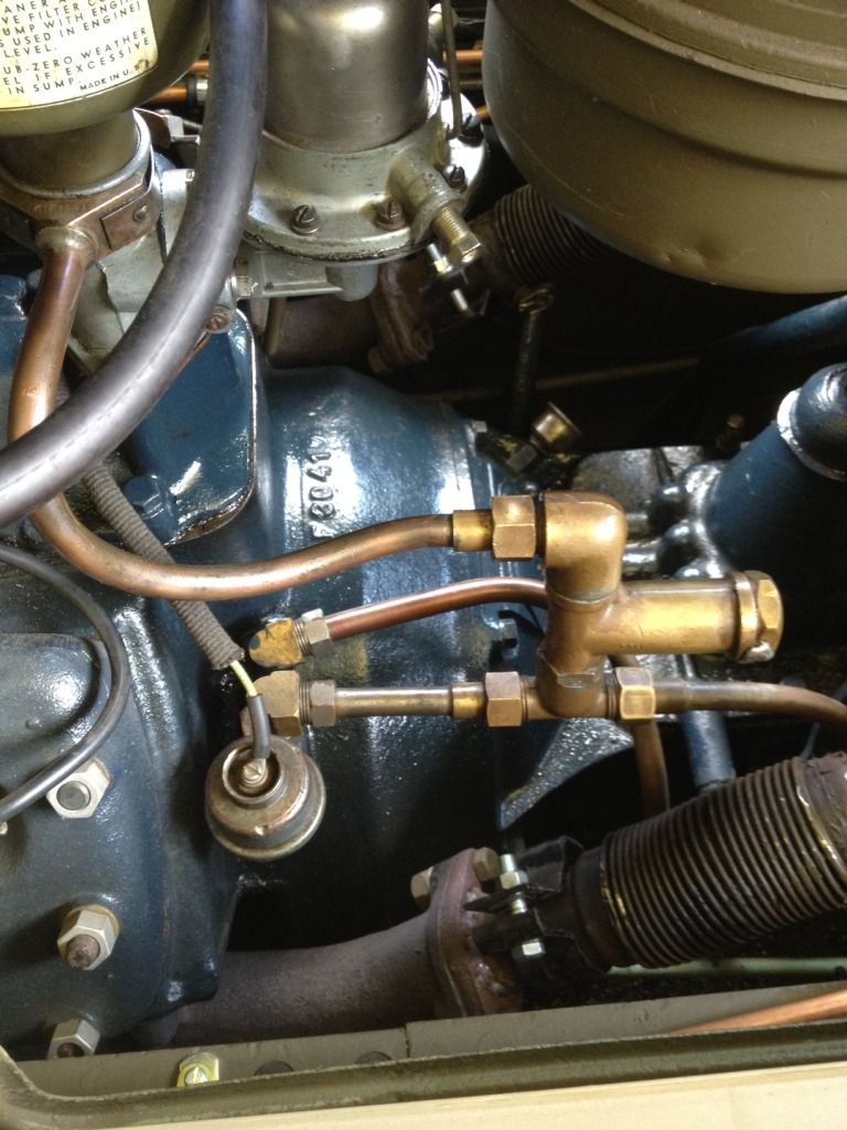 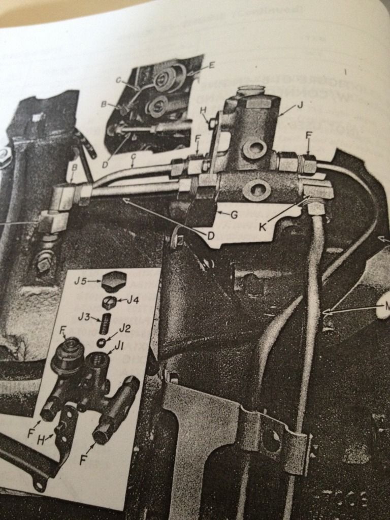 in the top photo this is the set up as the vehicle came from the British Army, as far as I know. I have not altered it and the soldered seal on the pressure relief valve was stamped with an inspectors mark. It would appear to me, that the British, or a later Ford modification, has directed the oil relief flow to the point above the fuel pump as you can see in the photo. It is this oil flow, that I believe is finding its way into the fuel pump and flowing out of the petrol relief hole. The set up as seen in the photo from the TM is quite different. It would appear that the relief valve is on the other side of the two pipes to mine. In other words either the pick up pipe has been changed on my engine, about 12 months later than the date of the TM, or it has been muddled by British Army when they made this mod. So in the TM photo, it would appear that the pipe nearest in the photo is the return to the engine and the outlet pipe to the oil cooler has the oil pressure gauge and the relief valve attached to it. I assume if there is a restriction in this circuit it returns through the brass interconnection back to the return into the crankcase. On my engine , you will see that my pressure gauge and relief valve are on the other pipe and the relief has been redirected to the oil filler pipe. It may well be that I have followed the schematic in the TM ( another diagram not illustrated here) and connected the pipes on the flexible section of the oil cooler lines the wrong way around. I can check this today, but it still does not explain why these pipes are completely different from the set up in the TM. Go figure, and if you can work it out, please let me know. Meanwhile, I plan at some stage to remove both pipes and check which way the oil flows from my engine left or right pipe then I can connect the cooler pipes the right way around for sure. Last edited by andrew honychurch; 05-08-12 at 09:55.
|
|
#9
05-08-12, 20:33
|
||||
|
||||
|
Attached a shot of my oil cooler lines even though its a different setup. Yours appears to have a second breather on the driver side of the rear engine. I've got that part connected to the top of my differential and don't have another breather on the engine other than the one where the oil enters the engine at the fuel pump where you are having the leak.
From your routing, the by-pass is open and sending the oil to the upper line. It's leaking is probably related to either the engine having too much internal pressure or air is coming in from the second breather and exiting from the higher original factory one and causing issues with the oil trying to flow inward against it. Not real sure what the purpose of the alternate oil route would be since I've never seen that on another vehicle so far. If it was providing essential oil, they wouldn't have made it only functional when the valve was in by-pass mode. Can you open the lines up front and confirm that oil will flow from the oil cooler lines? Or do you have the oil cooler shut off by manual lever if still installed? I don't have the levers on mine so can't turn them off if I wanted to.
__________________
David Gordon - MVPA # 15292 '41 Willys MB British Airborne Jeep '42 Excelsior Welbike Mark I '43 BSA Folding Military Bicycle '44 Orme-Evans Airborne Trailer No. 1 Mk. II '44 Airborne 100-Gallon Water Bowser Trailer '44 Jowett Cars 4.2-Inch Towed Mortar '44 Daimler Scout Car Mark II '45 Studebaker M29C Weasel
|
|
#10
05-08-12, 21:26
|
|||
|
|||
|
I believe that the reason for the bypass was to protect the engine in the event of a plugged oil filter or crimped cooler line. If that situation occurred then it would simply bypass the cooler/oil system and still lubricate the engine. Your system would not do that. Rather the oil would just dump through the filler/breather tube back into the pan, doing nothing for the bearings.
Is there any chance your filter or cooler lines are partially blocked? Can you get a mechanical oil gauge on the return side, just before the engine, and confirm what the oil pressure is coming back into the engine? 80 psi at the relief would indicate to me that there is a flow problem either coming back to the engine. The flatheads generally would not generate that much pressure.
|
|
#11
05-08-12, 22:14
|
|||
|
|||
|
Could a faulty spring or adjustment in the oil relief valve also contribute to the high oil pressure?
Last edited by Michael R.; 05-08-12 at 22:20.
|
|
#12
05-08-12, 22:28
|
|||
|
|||
|
You are right Micheal. The relief valve in the block (front of the valve gallery, ford group 6666) should regulate the oil pressure to about 30 psi or so. I can't seem to find the answer right away as to whether the oil relief valve comes into play after the oil exits the engine through the cooler/filter and then back into the engine, or if it regulates it before the oil leaves the block. If it is after, then the problem could still be with a filtration/cooler blockage. Does anyone have a good illustration of the path of flow on a Flathead lubrication system?
Adjustment or repair of the relief requires the removal of the intake manifold. Last edited by rob love; 05-08-12 at 22:39.
|
|
#13
05-08-12, 23:10
|
|||
|
|||
|
Quote:
I have not had any opportunity to look at it today, as we have been watching Olympics...family things. But will check this all out tomorrow. One thing to bear in mind is that this oil was not pouring out on the 20 mile road run. Maybe the oil cooler has fouled up and is causing a restriction. Although I have blown air through and it pushes oil back out pretty easily. I really appreciate ALL your help and ideas. I will report back asap when I have got to look at it in more detail. ps David, no taps on the later oil coolers to shut off supply.
|
|
#14
05-08-12, 23:14
|
||||
|
||||
|
Hi Andrew,
From what you were telling me when we met yesterday, I have worked out a possible explanation. The oil will not flow to the cooler if it is cold, it will lift the relief valve in the remote valve block and return to sump, via dipstick tube. This might explain why when you drove the carrier, it did not show signs of leaking through the lift pump hole under the diaphragm, as it was hot oil and not flowing back via the tube. If I could find my T16 book I might be more sure but looking at a Windsor book at present.
__________________
Richard 1943 Bedford QLD lorry - 1941 BSA WM20 m/cycle - 1943 Daimler Scout Car Mk2 Member of MVT, IMPS, MVG of NSW, KVE and AMVCS KVE President & KVE News Editor
|
|
#15
05-08-12, 23:24
|
|||
|
|||
|
To be clear I thought I would just summarise the issue
1. My set up appear to have the oil pressure and relief valve on the other elbow to the book and David Gordons. This is odd as I assume only one of these elbows flows pumped oil out, the other is a return. 2. Which elbow flow oil out? 3. Did the arrangement of these oil pick ups change for some reason? 4. If mine is taking oil from the wrong elbow it will be sending it back in against the oil trying to flow out? 5. If I have followed the schematic when I hooked up the cooler lines, I may well have got the oil flowing into the wrong union on the cooler. Could this be affecting my flow rate through the cooler, and causing the relief valve to operate and dump oil onto the fuel pump? Hope thats all clear thanks A
|
|
#16
05-08-12, 23:28
|
|||
|
|||
|
Quote:
Very odd!! On top of the Dingo playing up, I am not having a good few days!
|
|
#17
05-08-12, 23:32
|
||||
|
||||
|
Quote:
Are you positive there is a thermostat in the cooler? Not one in a Windsor, although that means nothing. The way it works is when oil is cold, it has higher viscosity and lifts the relief valve in the t-piece, then as the oil warms and thins, goes straight through the cooler.
__________________
Richard 1943 Bedford QLD lorry - 1941 BSA WM20 m/cycle - 1943 Daimler Scout Car Mk2 Member of MVT, IMPS, MVG of NSW, KVE and AMVCS KVE President & KVE News Editor
|
|
#18
05-08-12, 23:32
|
|||
|
|||
|
Is there a cross section view of the relief valve in the T-16 Manual ?
Attached is the cross section view found in UC-F1, which shows the input flow direction and return. The second image is a standard set-up with an electronic oil pressure sending unit attached in the normal fashion for the Ford Canada UC Mk. I* and Mk. II*. Note that for correct installation in the Canadian Carrier, the high pressure would be on the left side when facing forward, which is as you (Andrew) have it positioned on your block. Your oil cooler plumbing appears to have a direct connection to the return side of the engine block from your cooler. Last edited by Michael R.; 05-08-12 at 23:49.
|
|
#19
06-08-12, 00:49
|
||||
|
||||
|
Great photos chaps, always nice to see detail.
Here is my take on the PRV: Originally Flathead V8s only had one PRV, that in the valley of the block. Oil passed up from the pump then turned right just under the tappings in the top of the bell housing and went into the valley on it's way to oil the bearings etc.. (not the rear main though), pressure was controlled by the PRV at the front on the valley. When you break into the oil system before the PRV, (which you do when you utilise the bell housing tappings) that oil pressure is unregulated. When they fitted the oil cooler, the additional PRV was added to protect the cooler from bursting due to over pressure in the event of a cooler / pipe blockage and possibly as a form of cooler bypass when the oil was cold and more viscous (not on Yours Andrew, that is just for safety) However on later wartime Flatheads ford came up with a proper PRV system as part of the pump, thus oil at the bell housing is regulated. What pump did you fit Andrew? If you have the later one you can disable the cooler PRV as you are already protected. If not then I bet your main PRV at the front on the valley is set higher than the PRV in the cooler line causing the cooler PRV to be permanently off it's seat, it shouldn't be relieving in normal operating conditions. To be honest, the pressure transmitter should be mounted on the return from the cooler to give the true engine oil pressure, I would change yours asap if I were you. As it stands at the moment your engine oil pressure could be on it's knees and you wouldn't know a thing about it! If your cooler never gets hot, remove the aforementioned pressure transmitter and use a thin screwdriver to check that your oil gallery blanking plug is installed. When you poke through the tapping you should bottom out after 1.5" or so, if it goes in much more then oil can travel up from the pump and right into the engine, it will have no interest in investigating the cooler :-) Ps. Any more photos your your beautiful engine?
__________________
Alastair Lincoln, UK. Under Restoration: 1944 No2 MK2 Loyd Carrier - Tracked Towing 1944 Ford WOT6 Lorry The Loyd on Facebook Last edited by ajmac; 06-08-12 at 01:13.
|
|
#20
06-08-12, 01:49
|
||||
|
||||
|
Hey Andrew,
Copied your image back in with an arrow pointing at the thing I was thinking might be a second breather since it looks really similar to the one on my rear deck going to the differential. My coolers should be the 1st pattern but I have 2nd pattern as they were all I could source when I did the restoration. They don't have cut-off levers but I didn't realize that all of the later carriers omitted that feature. Originally the T-16 had issues with oil coolers rupturing so the regulated pressure in the block being discussed might have been the fix. And also why they didn't need the cut-off lever anymore. My oil pressure has always seemed low to me being 15-25psi max even at full power for liftoff. Had thought it had something to do with my sending unit so if they run at lower psi by design, that makes me feel better. My jeep always has higher pressure right from the start and that's what I've been used to. Your surge of high pressure could have been from a blockage in the line due to the by-pass being stuck. It broke free and is now stuck open so oil is going to your alternate route in the breather. I opened mine up before posting this and it contains a large metal ball at the bottom with a 1.5" long spring on top. A slotted plug down the well is screwed in over the spring and ball and then there is the large visible hex head on top of everything which is visible in my engine photo earlier in the thread. Don't have a diagram but it's fairly straight forward how the by-pass works. Pressure against the ball compresses the spring and allows the oil to take the other path. In terms of direction, I think it flows from the line closest to where you and I have our oil senders attached. This is the revised location. Originally it was located on top of the housing beside the by-pass which would be reading pressure as it came back from the oil cooler as opposed to engine side oil pressure which is more important.
__________________
David Gordon - MVPA # 15292 '41 Willys MB British Airborne Jeep '42 Excelsior Welbike Mark I '43 BSA Folding Military Bicycle '44 Orme-Evans Airborne Trailer No. 1 Mk. II '44 Airborne 100-Gallon Water Bowser Trailer '44 Jowett Cars 4.2-Inch Towed Mortar '44 Daimler Scout Car Mark II '45 Studebaker M29C Weasel
|
|
#21
06-08-12, 02:03
|
|||
|
|||
|
Quote:
|
|
#22
06-08-12, 04:18
|
|||
|
|||
|
From some U.C. books.
__________________
Bluebell Carrier Armoured O.P. No1 Mk3 W. T84991 Carrier Bren No2.Mk.I. NewZealand Railways. NZR.6. Dodge WC55. 37mm Gun Motor Carriage M6 Jeep Mb #135668 So many questions....
|
|
#23
06-08-12, 04:23
|
|||
|
|||
|
Of couse your system will be slightly different, so move with care.
Tony Smith is right, photos are better than me telling you. The info regarding adjusting the valve is referring to ports marked the same as Michaels picture of the valve. David that "breather' you have arrowed is the grease cup for the thrust bearing.
__________________
Bluebell Carrier Armoured O.P. No1 Mk3 W. T84991 Carrier Bren No2.Mk.I. NewZealand Railways. NZR.6. Dodge WC55. 37mm Gun Motor Carriage M6 Jeep Mb #135668 So many questions.... Last edited by Lynn Eades; 06-08-12 at 04:38.
|
|
#24
06-08-12, 07:16
|
||||
|
||||
|
Thanks Lynn, something new for me to research as I have a hex bolt there for some reason. I probably filled the hole during restoration and promptly forgot about it....
Per Lynn's post below....I do remember fitting a sealed bearing so might have eliminated the grease fitting at that time. Thanks
__________________
David Gordon - MVPA # 15292 '41 Willys MB British Airborne Jeep '42 Excelsior Welbike Mark I '43 BSA Folding Military Bicycle '44 Orme-Evans Airborne Trailer No. 1 Mk. II '44 Airborne 100-Gallon Water Bowser Trailer '44 Jowett Cars 4.2-Inch Towed Mortar '44 Daimler Scout Car Mark II '45 Studebaker M29C Weasel Last edited by horsa; 06-08-12 at 15:59. Reason: Added info
|
|
#25
06-08-12, 09:12
|
|||
|
|||
|
There were two types of thrust bearings used, but a modern sealed bearing is probably the best. Then we are not inclined to over grease it, and end up with a stuffed clutch because it has grease in it.
__________________
Bluebell Carrier Armoured O.P. No1 Mk3 W. T84991 Carrier Bren No2.Mk.I. NewZealand Railways. NZR.6. Dodge WC55. 37mm Gun Motor Carriage M6 Jeep Mb #135668 So many questions....
|
|
#26
06-08-12, 09:22
|
||||
|
||||
|
Great info there chaps, so if Andrews PRV is set at 10psi like the manual suggests, but isn't being used to regulate hot and cooled oil mixing as the original design intended, rather just dumping oil over 10psi back to the sump via the filler then there is a problem.
__________________
Alastair Lincoln, UK. Under Restoration: 1944 No2 MK2 Loyd Carrier - Tracked Towing 1944 Ford WOT6 Lorry The Loyd on Facebook
|
|
#27
06-08-12, 09:56
|
|||
|
|||
|
Fantastic, what a great wealth of knowledge there is out there. Its as good as having you all here inthe workshop with me, but without out me having to crack the tinnies!
No seriously , thanks a lot all of you, there are some really interesting points here. I have to assume, maybe wrongly, that what I have is how it is meant to be on my vehicle. I cannot id the oil pump fitted to mine, as I have not an indpeth knowledge of what the other types look like, but as my vehicle is June 1944 and has the thermostatically controlled valves in the oil coolers , it seems that there may have been a change to the way the system is plumbed. At present , my best guess is that I have the correct set up but a blocked or restricted cooler. Remember, that during my first tests and run to War and Peace the cooler was getting hot, i.e working. Now it is not. I reckon therefore that the restricition is opening the relief valve and that is whay we are seeing too much oil being fed back through the filler neck. Much as I didnt want to do it, as its a pain in the arse job, it seems I will need to pull the cooler off and clean it once more with solvent to try to get it flowing .. Given the low pressures on these engines, its seems logical that it would not need much of a restriction in the cooler or lines to cause the PCV to operate? David, on the oil greaser, did you have a flexible pipe inside leading from this to the thrust bearing? If not, dont fit the greaser or it will dump into the bellhousing!! I hope to report back later chaps, many thanks Andrew
|
|
#28
06-08-12, 10:44
|
||||
|
||||
|
Good luck investigating.
Attached is a little single line sketch of the various Flathead V8 oil system layouts. Yours is the third one down, at least on the face of it! On a well designed modern oil sytem you would have a PSV (Pressure Safety Valve) around the pump to protect from dead heading, this would be the highest pressure setting in the system and shouldn't lift in normal operations. After the pump you would have the main PCV (Pressure Control Valve) for the system and after that the TCV (Temperature Control Valve) directing some oil to the cooler and mixing it with hot oil to maintain a set temperature before sending it on to the oil filter and the things you want to lubricate! You would monitor the line pressure after the filter just before the things you want to lubricate. In an automotive application it would be quite acceptable to combine the PSV and PCV into one PCV as part of the pump. PS. The rear main is fed directly from the pump discharge before it ever gets to the top of the bell housing, thats what makes fitting a full flow oil filter almost impossible.
__________________
Alastair Lincoln, UK. Under Restoration: 1944 No2 MK2 Loyd Carrier - Tracked Towing 1944 Ford WOT6 Lorry The Loyd on Facebook Last edited by ajmac; 06-08-12 at 11:38.
|
|
#29
06-08-12, 15:10
|
|||
|
|||
|
ok, so I have had time to investigate and this is what I have discovered.
1. The outlet pressure from the cracnkase/bellhousing is the nearest the left hand side of the engine, and feeds directly into my PRV. 2. I have established that I am getting flow back to the other elbow. 3. As the engine heats up, which takes a long while as I dont have thermostats in the cylinder heads, the oil cooler takes more of the flow and the relief flow to the filler tube slightly reduces. I hope and suspect that as the engine gets really hot there is less flow to this tube and more to the cooler. 4. I dont know quite why my system has been created, as its not in the TM but I think it probably works. MY suspicion is there is a design fault that means that the fuel pump fills up and if you operate on rough ground at speed as I was doing, it will spill out some of this oil 5. I can try to make a gasket for the fuel pump aperture which is better at resisting this oil flow. 6.I have oil pressure, I have oil cooling, and I have an engine that works, so until I can find a Chilwell ( or FORD USA ) mod sheet I think I am going to leave well along and try to avoid oil spillage by physical means. Thank you all for the help on this, and if the problem continues I will post again, but until I have got the engine really up to temperature I cannot say for sure whether this relief valve flow will cease. thanks
|
|
#30
14-08-14, 18:41
|
|||
|
|||
|
I am still struggling to work out why the British army modified the PRV set up as per mine on the above photograph. Of course I have no information on it as I have the original TM s . I have seen one other T16 with this set up, again ex British Army. I don't suppose anyone has any post war British manuals for T16's they could check in?
|
 |
| Thread Tools | |
| Display Modes | |
|
|


 Linear Mode

