|
#1
 17-02-13, 02:58
|
|||
|
|||
|
A couple of questions.
1) Does anyone know what companies manufactured the horizontal aerials? I have seen the wooden aerial reels with either white or black lettering, so am assuming at least two companies may have been involved. 2) Can anyone provide detail photos of how the connection is made between the end of the horizontal element and the aerial lead that feeds down to the set? Every photo I have seen of the aerial wound up on the reel shows the copper stranded element wound on one half of the wooden reel with the rubber shielded lead wound beneath it. The connection assembly is always hidden under the windings. The one aerial I have was butchered, with the connection point having been cut away and I would like to know if it is restorable, or easily replicated. Thanks. 
|
|
#2
17-02-13, 14:55
|
|||
|
|||
|
As requested. Of course now you'll need to find the full set of frequency ranges.
|
|
#3
17-02-13, 18:04
|
|||
|
|||
|
How many people know that the radio in the second picture is a Canadian WS-29 set
__________________
Roberta Jayne Melville CD II QJ MK I * universal carrier 1942 WLC Harley under restoration 1957 M38A1 jeep R.E.L. optical equipment Military manuals Field phones MK II 19 set (needs work) 4 MK III W-19 sets AN/PRC-9 CPRC-26 WS-29 componets WS-38 AFV WS-38 MK III WS-48 with generator WS-58 MK I MK V heliograph
|
|
#4
17-02-13, 18:16
|
|||
|
|||
|
Thanks Bruce. Yours don't look at all like the pile of poop I've got! The reel l have is for the 185 ft Aerial No. 1. What is wound around it is three sections of 7-strand copper wire. The smaller piece (about 12 feet) has a 1/2 " spade lug on one end. The other two pieces (about 20 feet and 50 feet) have a single insulator link fastened at one end. One of these links has an additional 2 feet of stranded copper wire fitted to it, ending in a threaded terminal post.
From what I can see from your photos, the only thing original left on what I have is the soldered loop connection of the stranded copper element wire to the surviving, black, insulator links. No trace at all of the insulated feeder line to the set, or how it was connected to the aerial element. I don't think I will ever need the full set of horizontal aerials, but I wouldn't mind tracking down a couple of the set eventually. Mind you, if I ever win a lottery and my lovely wife finally gets her dream kitchen, my perspective might change. David
|
|
#5
17-02-13, 18:34
|
||||
|
||||
|
Quote:
Seen it several times at Bruce's home. IIRC, he's still trying to find a No 29 xmitter.
__________________
PRONTO SENDS
|
|
#6
17-02-13, 18:55
|
||||
|
||||
|
Dave:
AE connection to the No 19 set was by a metal bit of rod roughly 1" long and roughly +/- 3/16" soldered to the free end of the horizontal AE. In effect, you would have an end fed dipole. The bit of rod fits into a "squeeze" type socket located on the rear of the set, where the F rods would go. Make sense?
__________________
PRONTO SENDS
|
|
#7
17-02-13, 18:55
|
|||
|
|||
|
Hello David
Here are a couple of scans from Wireless for the Warrior Vol.2 WS19 Horizontal Aerial 100ft No.5 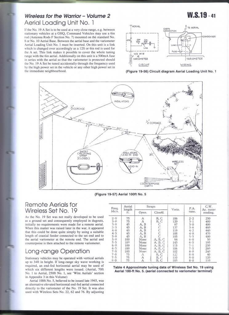 WS22 Horizontal 140ft Airborne 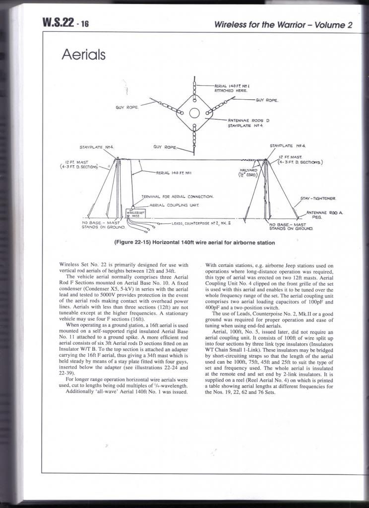 WS22 Horizontal Aerial 100ft No.5 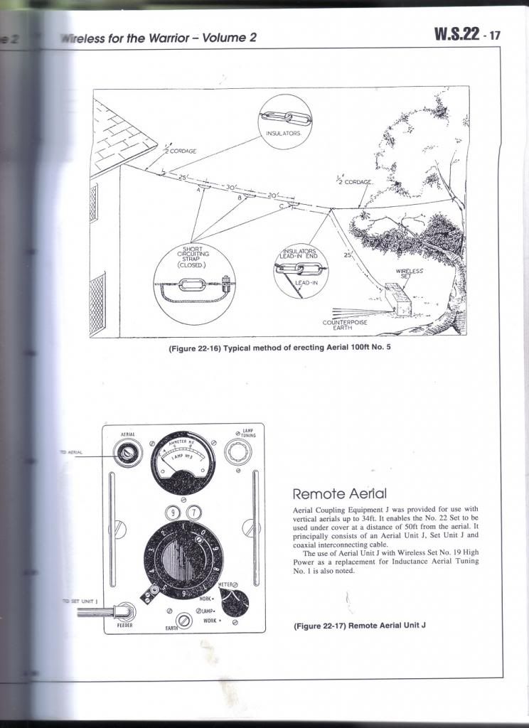 WS52 Ground Installation using Horizontal Wire Aerial 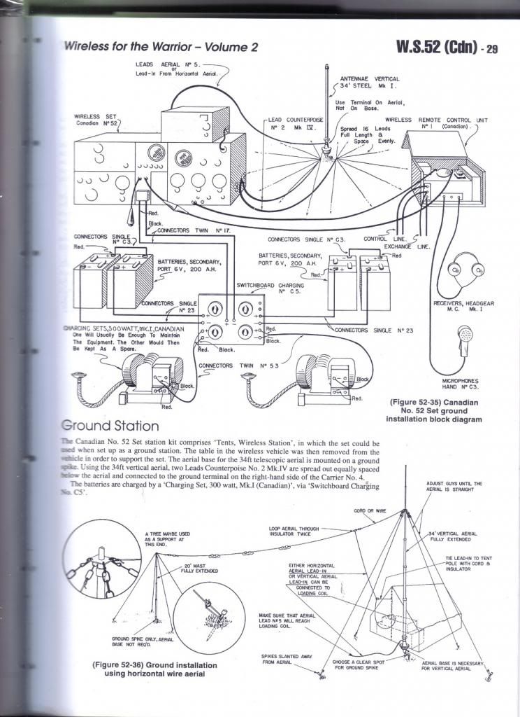 Here are some pictures of the Aerials Horizontal Four Sections (140ft) ZA/C00087. The sections could be bridged to make aerials of different lengths. The lead is rubber covered 10' long.   The connections on the lead. The plug on the left goes into any socket used for an 'F' Rod.  The plastic insulators (3) and breakable connectors.  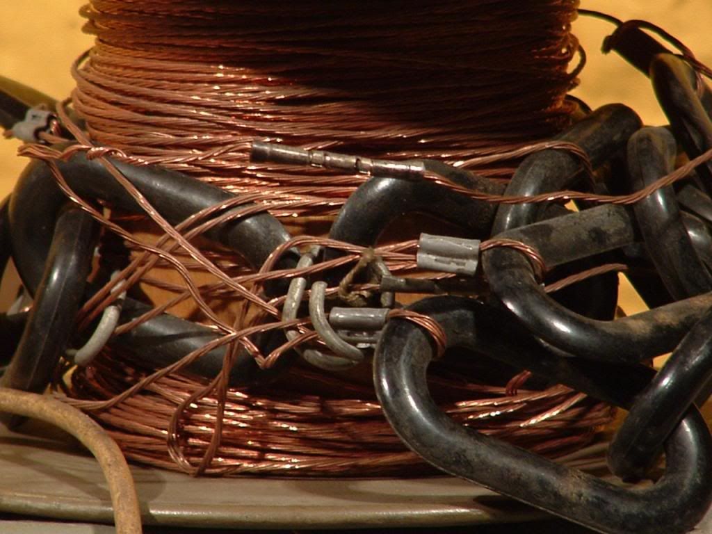 Geoff Last edited by Johnny Canuck; 17-02-13 at 19:06.
|
|
#8
17-02-13, 19:42
|
|||
|
|||
|
Quote:
Why yes Jon, I do happen to need the "A" set to complete it. Everything else is there. Sooooo....if anyone out there has, or can give me a solid lead on one I have lots of trades. Even a very nice W/T 62 set that Jon knows a little about.
|
|
#9
17-02-13, 20:41
|
|||
|
|||
|
So far for the WS-29 set I have found 2 B radios, 1 aerial tuning unit # C 2, 1 head set working instructions Wireless set No. 29, and Kits aerial gear No. C1.
I had heard that a number of the A sets had been buried because of the radiation hazzard. Possibly around the Winnipeg area. Bobbie J
__________________
Roberta Jayne Melville CD II QJ MK I * universal carrier 1942 WLC Harley under restoration 1957 M38A1 jeep R.E.L. optical equipment Military manuals Field phones MK II 19 set (needs work) 4 MK III W-19 sets AN/PRC-9 CPRC-26 WS-29 componets WS-38 AFV WS-38 MK III WS-48 with generator WS-58 MK I MK V heliograph
|
|
#10
17-02-13, 21:26
|
|||
|
|||
|
Quote:
One of my uncles worked for RCA during the war. He never worked on the W/T 29 but when I showed him my bits he instantly recognized it as the project being worked on 'downstairs'. The B set was designed to be used as a stand alone, short range set so it is a nice find just as is.
|
|
#11
17-02-13, 21:55
|
||||
|
||||
|
Quote:
I love to turn on my 19 sets, turn off the lights, listen to the dynamotor hum, and watch the dials glow. I'm still alive.
__________________
PRONTO SENDS
|
|
#12
18-02-13, 00:16
|
|||
|
|||
|
Quote:
|
|
#13
18-02-13, 02:48
|
|||
|
|||
|
Hello Geoff.
That drawing of the short circuiting straps on the sectional aerial is an exact match for the short wire I have and the other pieces with the single insulators now make sense to me. What I think I must have, are the scrap remains of a cut up 4-Section aerial. At some point somebody must have used an empty reel for the 185 ft aerial to store the bits on. So I guess I am right back at square one for finding a complete horizontal aerial. Now where did I put my 649 ticket?!? David
|
|
#14
18-02-13, 04:52
|
|||
|
|||
|
A counter poise Mk 2 or ground wire.....
Can someone explain in plain English what it is and what it does...? I am trying to read and understand the jargon. From what I have read and seen in the posting it seems to serve a some kind of horizontal signal reflector......ground plane..???? so a bunch of leads who are laid out radiating from the mast on the surface of the ground or use a deep rod stuck in the dirt as a ground...??? Thanks for the edification. Bob ...I should have paid attention when Jon gave us a WS 19 lecture at one of the CC bash !!!!
__________________
Bob Carriere....B.T.B C15a Cab 11 Hammond, Ontario Canada
|
|
#15
18-02-13, 05:30
|
|||
|
|||
|
Bob.
The counterpoise is intended to provide an effective grounding (earth) for the set during operation. This helps with the efficiency of the signal being sent out over the aerial. One could accomplish this by pounding a steel grounding stake into the ground and connecting the set to that, however, in a combat zone that action would have been as popular as having to go out in no-man's land during World War One and pounding barbed wire stakes into the ground. The counterpoise was used as a quiet alternative to all the noise making a hammer produced. The Working Instructions for the No. 19 Mk III explain the counterpoise as follows: " The use of an elaborate earth e.g. a radial earth, with the spokes not less than half the wave-length being used, will improve radiation markedly. Even a simple earth-pin near the vehicle will effect some improvement in radiation, and will avoid the noticeable drop in aerial current which would occur through people near the truck touching the parts of its chassis to which the set is earthed. An earth will also, in many cases, improve the signal-to-noise ratio on receive." Hope that helps. David
|
|
#16
19-02-13, 01:14
|
|||
|
|||
|
Every little bit helps me understand better.
Bob
__________________
Bob Carriere....B.T.B C15a Cab 11 Hammond, Ontario Canada
|
|
#17
19-02-13, 20:00
|
|||
|
|||
|
Geoff.
Further to your post here on Feb 17th and the Figure 22-15 Aerial Set Up. Are you familiar with that particular aerial system at all? The reason I ask is that many years back, I acquired a bag of aerial stuff, primarily because it contained a ground stake for the 20 and 34 ft masts, along with the associated mast base plate. When I got the bag of treasures home, I also discovered a set of steel guy stakes at the bottom of it and the PC numbers on the stakes matched those for the same item in the 19-Set Ground kit. I could not identify any other PC or ZA numbers on the other items in the bag and assumed they had nothing to do with the 19-Set at all so passed them on to another chap in town. The bag was a soft OD green canvas, somewhat tubular in shape about 4 feet long. Sort of a skinny duffle bag, held closed by either two or three canvas straps and buckles. The other items in the bag were a set of wooden, green poles about 2 inches in diameter, three or four feet long, each with a steel pin in one end and a corresponding socket hole in the other end. There was also two pairs of those square steel plates, each with four insulator/guy rope assemblies attached. The guy rope cords were not white like the ones seen in the 19-Set Kit, but were OD green. I could not for the life of me, figure out how the poles were anchored to the ground and if I split the pole sections up evenly, the entire thing seemed rather low, so I assumed there were some parts missing. Also, the bag was rather floppy when closed, with bits sticking out. Ended up swapping it for an NOS leather Aerial Bag for the 19 Set stuff I had and forgot about it. Guess I got rid of something special after all. So many toys for the 19-Set! So little space!
|
|
#18
20-02-13, 05:35
|
|||
|
|||
|
Hello David
Sounds more like improvised Post War tent poles. I'm no expert but I've not heard of wooden aeriel masts........... yet. Tent poles yes. The diagram you refer too mentions 'D' Rods which were about 3' in length, 7/8 diameter, threaded male/female. 'D' Rods were originally British and used to make up horizontal aerials and vertical antennae. The diagram explains it so I won't reiterate it here. This is a nearly complete 'D' Rod aerial set. The actual mast kit. Many of the items were still in their original wrappings or what is left of them.  Guys, pin bag and pins.  Misc parts in boxes, guys, ground spike and the insulated base mount.  An F Rod adaptor; this is not the one included with the kit, the one in the kit has the spring clamp at the top and a wing nut on the bottom both are threaded for the D Rod. This one can not be mounted directly above a stay plate as it would interfer with tightening the clamp. F rods were then added to make a 34' antennae.  The Canadians developed the 34' telescoping antennae and 20' mast to replace the D Rod set-up. circa 1944. 20' mast on the left, 34' antennae on right.    Geoff
|
|
#19
09-03-13, 19:50
|
|||
|
|||
|
was the Dogbone end insulator (ST, Bernard) used for the ant. installation?
ww2 comes in a wooden box. ceramic,12 inches long, 2 1/2 in dia. 
|
|
#20
14-12-13, 00:49
|
|||
|
|||
|
Quote:
The fixed length horizontal aerials on the 'H-shaped' wooden board winders are fairly simple and I believe I have the exact specifications somewhere. In the meantime (and from memory) they're all assembled from the same basic components: chain link insulators (which began as an RAF item and became ZA.4444 in army use), Wire, Electric, R4 (7 strand copper with a 1/2" lay), Cable, Electric, P11 (for the insulated downlead), and the metal plug that I can't remember the name of right now(!). All joints are soldered and uninsulated. The standard lengths were: ZA.11530 Aerial 70-ft No.1 covers 6.5 - 8.0 MHz ZA.11531 Aerial 90-ft No.1 covers 5.5 - 6.5 MHz ZA.11532 Aerial 110-ft No.1 covers 4.5 - 5.6 MHz ZA.11533 Aerial 150-ft No.2 covers 3.45 - 4.5 MHz ZA.11534 Aerial 185-ft No.1 covers 2.6 - 3.5 MHz ZA.11535 Aerial 250-ft No.1 covers 2 - 2.65 MHz I cannot remember offhand if the length includes the downlead, but I suspect it does. The 150-ft aerial is No.2 because there was an earlier aerial (for WS 1 or 11?) that had a different method of connection to the set (probably a spade terminal). Later on, Aerial, 100-ft, No.5 was issued, this was divided into sections using insulated links with clamp-on wire bridges so that one end of the aerial could be lowered to allow the length to be altered when changing frequency without the need to swap-out the entire aerial. The pre-set lengths were: 25-ft, 45-ft, 75-ft and 100-ft and the 25-ft section also acted as the lead-in (a spare 2-link chain insulator was issued to attach the halyard at a suitable point when hauling up). This aerial was entirely uninsulated (Wire, R4) and terminated with a plated brass spade connector - usable with aerial base No.10 (and others that had a screw terminal) or the later "Plates, Connector No.2A" variometer adapter with the screw terminal and bakelite "castle" insulator. They were all "general purpose' aerials and issued with a variety of wireless sets - mainly truck or command vehicles where skywave communication was used. Components were also issued separately for the larger radio trucks (WS12, 33, 53, etc), and included insulators (1, 2 and 3-link), cordage, and Wire, Electric, R4 (in a mysterious 41-yard packet), plus Cable, Electric, P11. Higher power sets came with Wire, Electric, R7 and Cable, Electric, P13 - heavier wire and (in the latter case) thicker insulation. The 41 yards looks like a peculiar length until you realise it's a quarter wavelength at 2MHz and two packets are all you need for a dipole at the lowest frequency the set will cover. I suspect the "Aerial, 100-ft, No.5" was a clone of the Canadian "ZA/C0087 Aerial, Horizontal, 4 Section" issued with the WS52 (much like the later "Mast, Telescopic 27-ft" is an obvious development of the Canadian 34-ft telescopic mast of WW2 vintage). Chris.
|
 |
| Thread Tools | |
| Display Modes | |
|
|


 Linear Mode

