|
#1
 20-12-15, 04:32
|
|||
|
|||
|
I thought a bit about posting in this thread rather than the Restoration Thread for the WIRE-5 elsewhere, but decided here was best as I am pretty sure these items are not exclusive (though most definitely elusive) to the WIRE-5.
If anyone has a set of these, or a good clear photo, please post. These mountings come as a pair, with Table Mounting Strips and are used to hold the 19-Set Carriers, Sets, No. 23 (the 'Bread Board') to the Wireless Table inside the WIRE-5. They look rather like a small steel box channel, with a slot cut the length of the top and fittings on the bottom to bolt it to the top of the wireless table. Support straps go top and bottom of the table as well to strengthen it. The front ends of the steel channels have spring clip assemblies fitted to them with a metal tab. They spring upwards in the 'locked' position and the tabs are pressed and held down to unlock them. For those of you lucky enough to have the Carriers, Sets, No. 23, if you look at the bottom at each end of the main board, you will see a steel plate assembly with a strip of steel rod welded along the end. It is these rods that are slid into the slots on the top of the Mountings, Carriers No. 1 to secure the 19-Set assembly to the wireless table. When the rods reach the back of the Mountings channels, the clips pop up at the front of the mountings and engage the leading edge of the Carriers, Sets No. 23, thereby locking it in place. Not one set of these mountings was to be found in all of the boxes at Princess. I even crawled inside a couple of upside down ones to check them out. You could always see where they had been located on the tables and Princess did not seem to be concerned about stripping parts out of the boxes for separate sale, so my best guess is that the military deemed them essential wireless equipment parts and removed them themselves before the wireless trucks were disposed of. Pity. Wonder if they follow a similar policy today when disposing of radio vehicles? David David 
|
|
#2
20-12-15, 05:15
|
|||
|
|||
|
Quote:
I think that I can assure you they do. IKEE components are controlled goods. Very few radio vehicles are disposed of in the first place.....most SMPs these days go to the prisons for dismantling.
|
|
#3
20-12-15, 15:42
|
|||
|
|||
|
They do have four thin metal strips to mount top and bottom of the table as Dave says.
|
|
#5
21-12-15, 05:45
|
|||
|
|||
|
In the event there are some WIRE-5 wireless table owners out there with rotted table tops, or they are so full of holes they look like swiss cheese, maybe we can get it all sorted out with a group effort.
From what I can see on my 'Bread Board' the two Mountings would have to be spaced about 35 inches apart on their centre lines. Can you measure the spacing between the four bolt holes on the feet for us? If we can rough out the spacing pattern for the Mounting holes, somebody with an original table could compare/match out measurements to holes on an actual table and confirm their actual location on the table top. With outside dimensions for the table top and Mountings sorted out, it should be easy enough for replacement wood to be cut for any table restorations needed out there. Probably a 1/2' or 3/4' plywood. The Installation Instructions make no reference at all to hole locations on the table, or any drilling information for that matter. They simply read: (7) Bolt the Mountings, Carriers No.1 to the Wireless Table, placing Table Mounting Strips on top and underneath the table and using eight 1/4"-20 x 1' long hexagon head bolt, nuts and lock washers. (8) Lift the whole assembly of Carriers, Sets, No. 23 (this is after the Wireless, PSU and Control Box are installed) by means of the carrying handles and slide into position on the Mountings, Carriers, No.1. Fasten the Carriers, Sets, No. 23 securely by pushing up the spring clips at the front left and right ends of the Carrier. Seems perhaps the Mountings holes were predrilled in the wireless table by Wilson Truck Bodies, or whoever built the tables. Life was so much easier then. David
|
|
#6
21-12-15, 07:25
|
||||
|
||||
|
I have a set that are surplus to my needs. Maybe we could work out a trade. I need the shock absorbers though. Did they use two or three on a setup? These came wired together like they were a unit.
The end holes on the metal strips are 11 7/8" center to center. The bolts that go through the table top are 2" long so the table could be 1" thick.
__________________
1940 Cab 11 C8 Wireless with 1A2 box & 11 set 1940 Cab 11 C8 cab and chassis 1940 Cab 11 C15 with 2A1 & Motley mount & Lewis gun 1940 Cab 11 F15A w/ Chev rear ends 1941 Cab 12 F15A 1942-44 Cab 13 F15A x 5 1942 cab 13 F15A with 2B1 box 1943 cab 13 F15A with 2H1 box 1943 Cab 13 C8A HUP 1944 Cab 13 C15A with 2C1 box 1943 Cletrac M2 High Speed Tractor MkII Bren gun carrier chassis x 2 Last edited by cletrac (RIP); 21-12-15 at 08:26.
|
|
#7
21-12-15, 16:19
|
|||
|
|||
|
Nice photo Dave. It struck a bell and I went poking in the Working Instructions for the Mk III 19-Set. Sure enough, in the 'group photo' at the back of the manual of all the Wireless Truck kit, there was the set of Mountings and they appear to be fastened together.
Just checked the spacing for the outer two holes on my Carriers, Sets No.21 and they are only 9 or 9.5 inches apart (they are starting to splay out a bit with age and I better address that soon), so for these Mountings, they seem to have spread the distance between the rubber feet to compensate for the wider load with the Carriers, Sets, No. 23 added to the mix. Could you check one other thing while you have your Mountings handy? The 'standard' feet on my Carriers, Sets No.21 are 7/8" wide. Are the ones on your mountings the same width, or did they beef them up a bit as well to handle the extra load? I think I ran across one lone foot assembly years ago that was much fatter than any of the others I had with my 19-Set gear and I tossed it assuming it was not correct. Now I am curious to see just how dumb I might have been back then. Cheers, David
|
|
#8
21-12-15, 17:12
|
||||
|
||||
|
The feet are 7/8" wide.
__________________
1940 Cab 11 C8 Wireless with 1A2 box & 11 set 1940 Cab 11 C8 cab and chassis 1940 Cab 11 C15 with 2A1 & Motley mount & Lewis gun 1940 Cab 11 F15A w/ Chev rear ends 1941 Cab 12 F15A 1942-44 Cab 13 F15A x 5 1942 cab 13 F15A with 2B1 box 1943 cab 13 F15A with 2H1 box 1943 Cab 13 C8A HUP 1944 Cab 13 C15A with 2C1 box 1943 Cletrac M2 High Speed Tractor MkII Bren gun carrier chassis x 2
|
|
#9
21-12-15, 18:09
|
|||
|
|||
|
Thanks David. Guess I didn't throw out anything special after all.
Oh, they only used two of these mountings (a mount, 2 x feet, 2 x straps and four 1/4" hardware sets), one on each end of the Carriers, Sets, No. 23, to install it on the wireless table. Supplies were probably stocked as complete Mounting Kits bundled together, as well as on an individual item basis to be issued as needed. David
|
|
#10
21-12-15, 20:11
|
|||
|
|||
|
Yes, these are a required part of the kit needed to mount the Carriers, Sets, No. 23 to the wireless table.
As an aside to all, and forgive me if I mentioned this somewhere else on the Forum, in a Galaxy far, far away, but with regards to the little u-shaped rubber/steel foot assemblies used with these Mounts and all the steel Carriers, Sets for the 19-Sets, they need to be bolted down when under load. If they are not, over time, the load bearing down through the centre bolt spreads out towards the two steel foot plates, pulling on the two rubber pads in the middle. The first sign of this taking effect will be that the steel plates of the feet no longer sit flat on a table or bench but start to curl and point upwards. If left unresolved, they will simply tear apart. One way to prevent this is to cut two strips of 1/2" or 3/4" plywood long enough to reach both foot assemblies on one side of your Carriers. Countersink appropriate holes and from the bottom up, bolt the plywood strip to the feet. That will stop any further spread/disintegration of the feet and still allow you to move the set anywhere you want to as needed. The design of these feet in this regard seems to be a bit of a weak point. A better system is the round rubber donut assemblies used in a lot of electronics, where the load transfer is straight down and then out around the circumference of the donut equally. Anyway. Save your feet. Bolt them down. David
|
|
#11
22-12-15, 03:10
|
|||
|
|||
|
Based on the information gathered so far on these mountings, I have drawn up the attached template of the probable hole pattern which should be found on any original Wireless Table that had the Carriers, Sets, No. 23 'Bread Board' mounted on it for the 19-Set. The template was drawn in centimetres, so the orientation of the holes to one another should be proportionally correct.
If any of you have original wireless tables for the WIRE-5 15-cwt Wireless Truck, can you check the table to see if you can locate this pattern of holes? If the top of the table is in tough shape, or bears a lot of holes, it might be worth looking underneath the table where the surface might be better protected. The top or bottom might also bear the shadows from the steel Table Mounting Strips used to reinforce these holes. Should you find these holes on your table: (1) Please confirm the dimensions shown for the hole spacings. (2) Please provide measurements from the four edges of the table top plywood to the centre lines of the two vertical rows of Mountings holes and the centre lines of the foremost and rearmost horizontal hole lines. This will allow anyone restoring one of these tables in the future (or building a new clone) to correctly orient exactly where the Mountings, Carriers No. 1 should be located on the Wireless Table. Best regards, David
|
|
#12
25-12-15, 01:15
|
|||
|
|||
|
Quote:
Later use of the vehicle with other sets would have added extra holes or possibly led to the replacement of the tabletop with a new piece of plywood to give a smooth surface with on awkward holes. Chris.
|
|
#13
29-02-16, 00:32
|
||||
|
||||
|
Here's a few on ebay.
__________________
1940 Cab 11 C8 Wireless with 1A2 box & 11 set 1940 Cab 11 C8 cab and chassis 1940 Cab 11 C15 with 2A1 & Motley mount & Lewis gun 1940 Cab 11 F15A w/ Chev rear ends 1941 Cab 12 F15A 1942-44 Cab 13 F15A x 5 1942 cab 13 F15A with 2B1 box 1943 cab 13 F15A with 2H1 box 1943 Cab 13 C8A HUP 1944 Cab 13 C15A with 2C1 box 1943 Cletrac M2 High Speed Tractor MkII Bren gun carrier chassis x 2
|
|
#14
29-02-16, 00:45
|
|||
|
|||
|
Whiskey Tango Foxtrot Question Mark Over.
|
|
#16
29-02-16, 02:15
|
|||
|
|||
|
"I refer the honourable gentleman to my previous reply."
They are junk - rusty, and missing the shock mountings (disintegrated) and reinforcing strips (presumably still attached to the missing remains of the shock mountings). P.T.Barnum was right! Chris.
|
|
#17
29-02-16, 07:04
|
|||
|
|||
|
Wasn't sure how to respond, I'll assume the gentlemen with the opinions are not actually interested in buying anything.
If any of you sell something of questionable value I'll try to do the right thing and say nothing insulting; like my mom taught me fifty years back. Also I think it's unobtainium not 'Plutonium' first you'd need a special licence to sell that stuff and secondly I think the stuff is sort of dangerous, no? Maybe something constructive.............. like what a complete set in original box with shocks and plates is actually worth, then the rest of us that have no idea might be able to get an inclination of what they are actually worth. Geoffrey Truscott aka Johnny Canuck Canada
|
|
#18
02-03-16, 03:04
|
|||
|
|||
|
Quote:
What is the market price on these things? Here is a little test. I have the two in the photos below in perfect condition, C/l\ marked. Not shown in the photos are 4 of the thin strips that go with them. First person who wants them for $20 (plus actual postage of course)for their own use or collection (not so they can merely re-sell them) can have them. And that is Canadian dollars, cause I am in Canada. Not American dollars because they are 45% more. If someone PMs me and takes them, then we'll know the price is somewhere between $20 Cdn for a perfect pair, and $200 US for the set on ebay. I hope I don't offend you with this post Geoffrey, and believe me, I have edited it a few times before hitting the "post" button.
|
|
#19
02-03-16, 03:24
|
|||
|
|||
|
OK, so it didn't take long for someone to reply with an I'll take them. So I guess we know that a new old stock set is worth $20 (Cdn).
Now for a short rant: seems like we don't see a lot of young people in this hobby...haven't for a while. I wonder if the pricing on things has maybe got a little out of hand, and makes trying to contemplate a project as financially un-achievable. I think I forgot to take my meds last night.
|
|
#20
02-03-16, 04:53
|
||||
|
||||
|
Sometimes I wish there was a "like" button on this forum. Rob; you would have got 2 likes today for the posts above, and one yesterday for the "coffee table" engine!
__________________
1953 M37 CDN 1953 M38A1 CDN W/WN 1967 M38A1 CDN2 W/WN 1968 M38A1 CDN2 W/WN
|
|
#22
02-03-16, 08:49
|
|||
|
|||
|
Quote:
You may well be correct on people being priced out of the hobby. Best Regards, Chris.
|
|
#23
02-03-16, 20:44
|
|||
|
|||
|
Well I guess the ones you had for sale are worth CDN$20.00
Personally I would really like it if all wireless items were less than they are. What gets me is when someone makes assumptions, ie: greedy, reseller when one doesn't actually even know the individual, I collect WW2 Wireless items used by the Canadians in WW2, if I buy an item of better quality I will try to 'resell' the lesser item for what I paid for it, if I can make 10% great. There are a few younger local fellows that I give items to or sell at a loss, because they show an interest. So what does that make me? So yes, some items are getting rarer and command a higher price, some items come from Europe and often cost more to ship than the item actually cost. All this adds to the cost, I'm not a government that runs everything at a loss. One should get to know someone before making judgements about their character or intentions. Making assumptions from thin air is usually only going to cause friction. Maybe I'll bite and see what happens, I'll change the sale to an auction and see what the WWW thinks they are worth, also note that I almost always offer 'Make an Offer' as I often really have no idea what an object is actually worth, I am always open to negotiation, keeps the riff-raff at bay and it is much easier to go down in price than up. I was going to sand blast the carriers, clear coat them and include the 2 metal strips I dug up but that would increase the value as there would now be the added value of paint, labour and time. Lots of the items we collect start out as 'Junk' but end up being classic pieces once finished, keep in mind that one mans junk is another mans treasure. I also spent some of my free time displaying parts of my collection at shows in Ontario in an effort to educate the general public on our roll in WW2 and perhaps actually interest some older or younger citizens in the hobby, so please don't judge me without having some facts first. Geoffrey 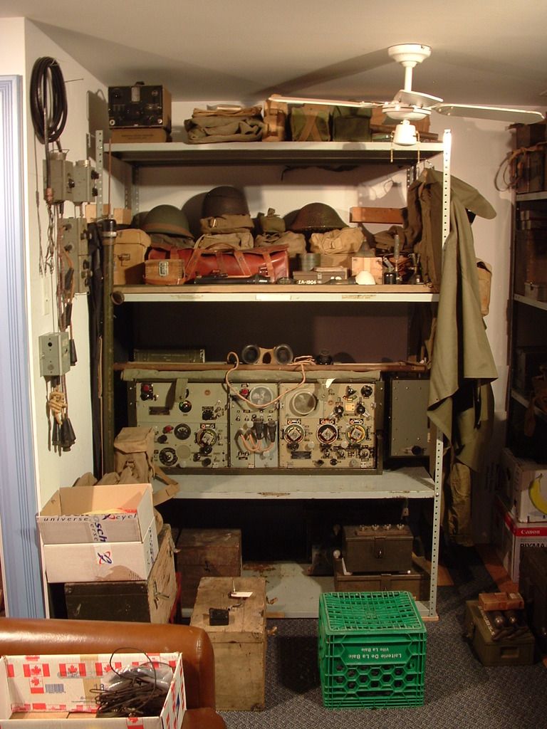   
Last edited by Johnny Canuck; 03-03-16 at 23:48.
|
|
#24
02-03-16, 21:13
|
|||
|
|||
|
Quote:
 Particularly things like the WS52 remote receiver that keeps appearing with a 250 GBP starting price. Eventually the seller may get tired of relisting it, but a realistic price is more like a fifth of that. (More if it has cables and PSU, of course, but the one shown does not.) I think some traders are holding out for the arrival of the "One true sucker" who will think they're getting a bargain. (Another long tradition is "spot the scammer" where very rare/expensive items get relisted using the description and photographs from the original eBay listing  - but that game is not played for laughs, and the scammers get reported to eBay (and sometimes the police) very quickly.) - but that game is not played for laughs, and the scammers get reported to eBay (and sometimes the police) very quickly.)  Chris.
|
|
#25
02-03-16, 22:50
|
|||
|
|||
|
Geoffry
I would really like to see what an actual auction would bring on items like these, so hope you try it. There is always that wild card that in the whole world, perhaps the second place bidder won't be around that day to propel the price up to what occasionally becomes insanity. But if there were to be two or three auctions of similar items a consensus could perhaps be reached. I'm not against capitalism...it's what North America is founded on. But where it gets crazy is when a mint set sells for a relatively high price, and then those who are not in the know assume their lesser condition examples are worth that. So the next really good one has to go for higher etc etc. It is a reverse incipient spin to the heavens. Last edited by rob love; 03-03-16 at 01:48.
|
|
#26
03-03-16, 01:23
|
|||
|
|||
|
|
|
#27
06-03-16, 04:58
|
||||
|
||||
|
I was following the auction to see what the open market price would be. But I was unable to locate the item in my saved list.
__________________
Jordan Baker RHLI Museum, Otter LRC C15A-Wire3, 1944 Willys MB, 1942 10cwt Canadian trailer
|
|
#28
06-03-16, 12:21
|
|||
|
|||
|
Quote:
http://www.ebay.ca/itm/-/152001881288? "This listing was ended by the seller because the item was lost or broken."
|
|
#29
06-03-16, 14:33
|
|||
|
|||
|
Yes 'Pulled by the Seller'
Prefer a mystery anyways. Sold to an MLU member. Geoff PS I think the going rate is $20.00 Canadian Peso'. Costs more to ship.
|
|
#30
01-05-16, 05:09
|
||||
|
||||
|
__________________
1940 Cab 11 C8 Wireless with 1A2 box & 11 set 1940 Cab 11 C8 cab and chassis 1940 Cab 11 C15 with 2A1 & Motley mount & Lewis gun 1940 Cab 11 F15A w/ Chev rear ends 1941 Cab 12 F15A 1942-44 Cab 13 F15A x 5 1942 cab 13 F15A with 2B1 box 1943 cab 13 F15A with 2H1 box 1943 Cab 13 C8A HUP 1944 Cab 13 C15A with 2C1 box 1943 Cletrac M2 High Speed Tractor MkII Bren gun carrier chassis x 2
|
 |
| Thread Tools | |
| Display Modes | |
|
|
 Similar Threads
|
||||
| Thread | Thread Starter | Forum | Replies | Last Post |
| Carriers can fly too | Peter Hommes | The Carrier Forum | 6 | 24-03-13 23:44 |
| Bens mountings and castings | shaun | The Carrier Forum | 5 | 07-09-11 10:48 |
| New Carriers | gary_bath_jr | The Carrier Forum | 10 | 16-11-10 19:05 |
| T-16's in Calgary Highlanders' Anti-Tank Platoon | peter simundson | The Carrier Forum | 18 | 14-04-07 22:47 |
| Our Carriers | Eric Szalanda | The Carrier Forum | 9 | 20-07-05 05:44 |


 Linear Mode

