|
|
|
#1
 19-04-19, 02:21
|
||||
|
||||
|
Bruce...you mean the Wheels?!
The center hubs of the wheels are wrong? You are telling me that the front is on the back, and the back is on the front!?! lol yes, the wheels are not attached. I just pushed them onto the axles so I could take a photo. I wasn't paying any attention to their position. Even the Axles/Diffs are not glued in place yet...the springs are just resting on them (again, for the purpose of a photo). Thanks...good eye...! 
|
|
#2
28-04-19, 05:57
|
|||
|
|||
|
Dave, assuming that the winch fairleads are same across the range of CMP's:
The two wire rope sheaves or pulleys are un-braked and measure in at 8 3/4inch diameter, 1 1/2inch thick, mounted on a vertical pin that passes through a boss top and bottom of both sheaves. This gives an overall height of 3 3/4 inches between the two mounting plates. The top mounting plate is as you have marked, going full width under the chassis rail. There is a lower plate that retains the mounting pins, it is the width of the two sheaves combined, and is basically a wide "U" section welded to the underside of the top plate. The bottom roller I have goes full side to side, but guessing the diameter would be the same, 3 1/2 inch. You know there is a set of fairleads on the front bumper as well? Rich.
__________________
C60S Austin Champ x 2 Humber 1 Ton & Trailer
|
|
#3
28-04-19, 18:21
|
||||
|
||||
|
Quote:
My "pulleys" are 12" x 2" scale size...so not too far off. Not bad for a guess. Sometimes, a bit bigger is better for scale assembly. I am still unclear about the second mounting plate. The "wide U section" you refer to. I can see part of it in my reference photos, but its still not clear to me how it mounts, or its actual shape and size. Its not a big concern, since I am not including every accurate detail, but... 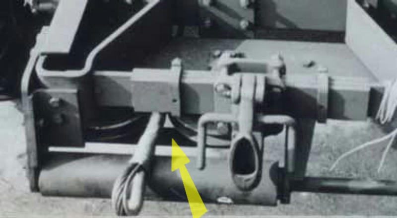 ... "fairleads"...whats that? You wouldn't be talking about that roller cable guide thingy? Is that what you refer to "up front"? 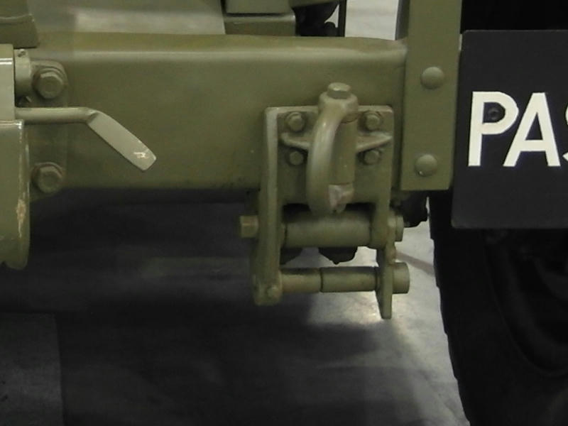 ... Where is the cable guide in the rear? Does it go here(photo)? Something is missing (on my model) to guide the tow cable under the frame. 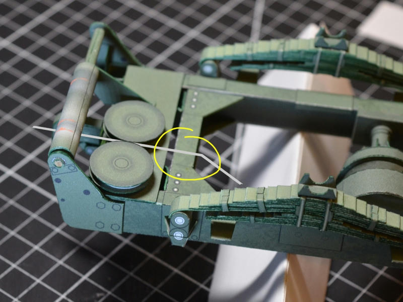
Last edited by DaveW; 28-04-19 at 18:29.
|
|
#4
29-04-19, 14:15
|
|||
|
|||
|
Better described as a Wide "L" shaped plate...this also holds the guide roller behind the sheaves.
Fairleads = Roller Cable Thingy, or any roller guiding the winch cable. The fairleads on the front, as shown in your pic, are nice and simple, they can be heavier and more complex than that: swing out rollers to pass the cable hook/eye through. Just in case.... the wire rope is fed around the outer sheave and forward to the fairlead on the front bumper for when winching is required at the front of the truck. Rich.
__________________
C60S Austin Champ x 2 Humber 1 Ton & Trailer
|
|
#5
29-04-19, 16:13
|
||||
|
||||
|
o-tay!
I have a much clearer understanding of this...thank you. I may have to reduce the diameter of my pulleys...I don't know. But I definitely have to add that lower plate. The fairlead is going to be a small problem, because even at 1/16 scale those rollers are less than 1 or 2mm diameter...and its hard to roll paper cylinders that small! I try to produce a "kit" that is self contained ...in other words, doesn't require you to introduce any other materials other than the printed paper parts I supply. Obviously some builders like to add other materials and alter parts using other materials to be more realistic or detailed. Its totally up to the builder...but I try not to expect that in my kits. My kits will produce a basic model, that is complete using only whats supplied. I may have to come up with a boxy stylized contraption instead. ... anyway, thanks again for your assistance. The help here has been great so far! Thanks again Ian!! ... I managed to finally sort out a basic design for the Drive Transfer Unit. Is that what we're calling it? lol The unit that connects directly behind the Transmission, and feeds the front and rear prop shafts/drive axles. And in this case, also supplies the Power takeoff for the Tow Winch. Being well hidden under the frame, I didn't want to get carried away with details or make the assembly too complicated, but I also had difficulty understanding its overall shape and how it sat within the frame. Now I understand. 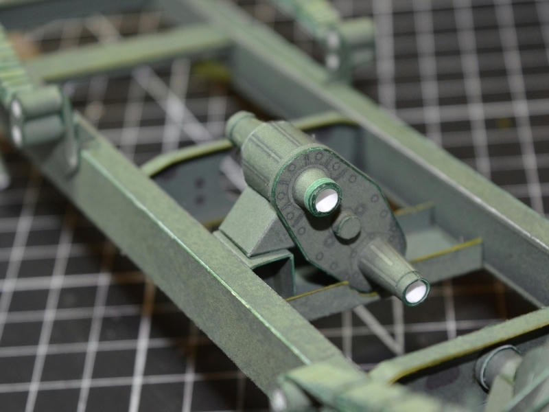 After that, I need to check the alignment of all the drive elements. No point in continuing if things didn't line up! I did build the basics of the power takeoff drive shaft, so I could test the closest component. And I wanted to get the Transfer Unit glued into place, so I needed that connection. But I also managed to confirm that the lower driveshafts(propshafts) and axles/diffs all line up. At least close enough to sort out the angles and the propshafts. 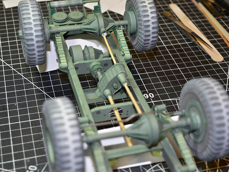
|
|
#6
29-04-19, 18:20
|
|||
|
|||
|
Dave,
The thing right in the middle of the above picture is almost universally called a "transfer box" in all wheel drive vehicles except in modern articulated loading shovels (and possibly some marine installations) where it is called a "drop box" as it's primary function is to lower the drive-line. A transfer box can be bolted directly to the back of the gearbox / transmission as in jeeps etc, or be separate as in most trucks. Also, to be pedantic the pulleys or sheaves are PART OF the fairlead assembly. The front fairlead has a pair of vertical rollers just behind the two horizontal rollers so that sideways loads can be taken. These are just visible in your post #16 middle photo. The use of pulleys at the rear is simply to allow for greater angles without damaging the rope by bending it too sharply. Great work though, please keep posting. David Last edited by David Herbert; 29-04-19 at 18:28.
|
|
#7
29-04-19, 18:40
|
|||
|
|||
|
I assume that Richard's photos show a winch equipped C60 which seems to have a bigger gap between the rear chassis cross member and the fairlead than a FAT. The top photo in Dave's post #16 shows the vertical legs of the heavy piece of plate that goes under the pulleys, bolted to the face of the rear chassis cross member. On the C60 the vertical legs are welded to the horizontal plate directly above the pulleys but also to something higher up - maybe another horizontal plate above the chassis rails ? There is then a gap of about 5" to the front of the rear cross member, leaving room for the brackets for the rollers to be extended upwards at about 45 degrees to reinforce the vertical plate.
David Last edited by David Herbert; 29-04-19 at 18:46.
|
 |
| Thread Tools | |
| Display Modes | |
|
|
 Similar Threads
|
||||
| Thread | Thread Starter | Forum | Replies | Last Post |
| Guy Quad-Ant | Dave Page | The Softskin Forum | 1 | 08-02-10 01:02 |
| Polsten Quad sights and technical info required | Chappers | The Gun Park | 2 | 11-10-09 19:55 |
| Ford (FAT?) Quad Gun Tractor | threadbear | The Softskin Forum | 7 | 01-12-08 01:13 |
| CMP quad + limber + 25 pdr gun | Richard Farrant | The Softskin Forum | 18 | 30-05-06 13:04 |
| Quad model | Snowtractor | The Softskin Forum | 2 | 05-07-03 08:48 |


 Hybrid Mode
